Upload
Home
Tubing and fitting guide for microfluidics
By Joshua Gomes
Best practices for connecting microfluidic devices to flow sources and other instrumentation.
The chip-to-world interface link to The chip-to-world interface section
Microfluidic devices are rarely used in isolation. Inevitably, they must be connected to external systems and instrumentation to function. In commercial microfluidic products, a custom system is often developed to automatically connect a microfluidic device to a lab instrument without user intervention. However, a significant amount of research and development is required to reach this level of automation.
The most common way to connect a prototype device to external instrumentation early in the development process is with tubing and fittings. While this sounds like a simple task, the world of fluidic connections is fragmented and complicated. We’ll discuss the pros and cons of different tubing architectures in this guide and offer some best practices to make the chip-to-world interface a little easier.
Interface Architecture
Capillary tube link to Capillary tube section
A capillary tube interface consists of a few components designed to make a robust fluidic connection. The tube (A) itself consists of a semi-rigid material, typically plastic, with a smooth, consistent exterior and a precise internal diameter. A nut (B) and ferrule (C) are slipped around the exterior surface of the tube. A port (D) is integrated into the microfluidic device. One method to install a fluidic port is to machine it directly into a device, but this is a slow, expensive option that risks generating particulate that can contaminate experiments. An alternative is to use glue or adhesive tapes, but these options can lead to problems with chemical compatibility and clogged channels. At Parallel we have a proprietary welding process that allows us to ensure clean, leak-free connections between the port and the device.
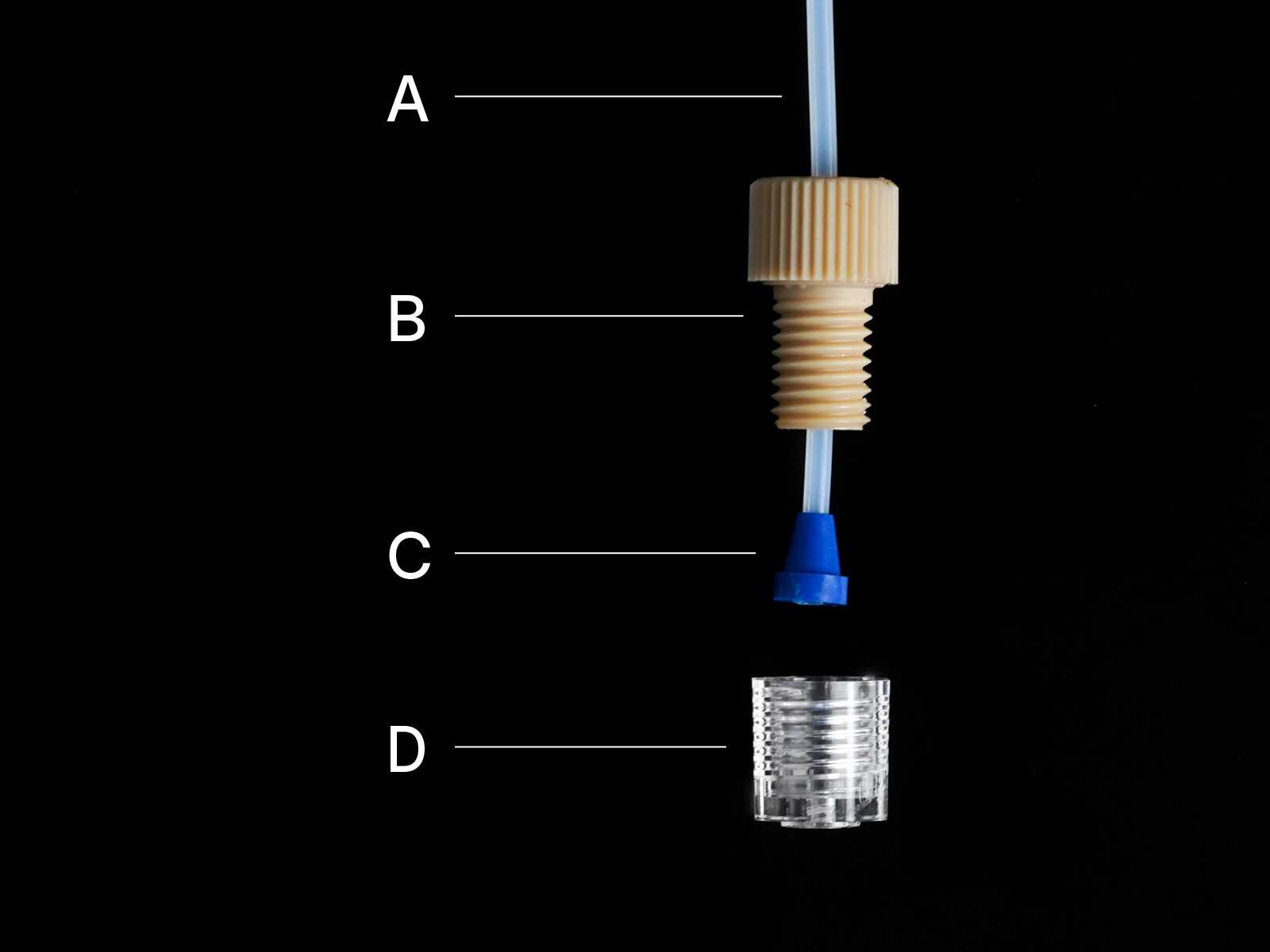
Flangeless 1/4-28 capillary tube interface - Disassembled
Capillary tube fittings were originally designed for use in the liquid chromatography industry, which demands high pressures, low dead volumes, and great chemical compatibility. Luckily, all of these properties are desirable for microfluidics! However, liquid chromatography applications may involve pressures far beyond normal operating conditions for microfluidics (in some instances up to 1000 psi or 70 bar) and are not typically subject to small size constraints. The design required to achieve such high pressure leads to interfaces that can be difficult to manage in small microfluidic systems. Despite these shortcomings, they are a great choice for demanding applications.
Pros
- Minimal dead volume
- High pressure tolerance
- A variety of inner diameters are available
- Many material options with good chemical compatibility
Cons
- Expensive
- Difficult to handle semi-rigid tubing
- Only compatible with other capillary tube interfaces
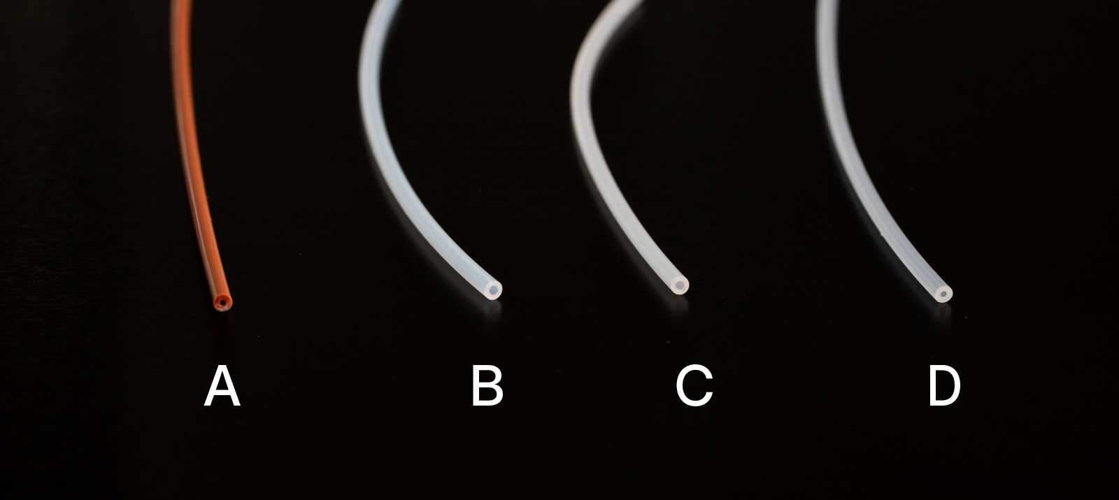
1/16" diameter capillary tubing: PEEK (A), PTFE (B), ETFE (C), and PFA (D)
Suggested Combination
It can be hard to know where to begin when sourcing capillary tube fittings because of the multitude of different styles, sizes, and materials available. For most microfluidic applications, we recommend the setup below as a starting point for the best combination of availability, performance, and ease of use.
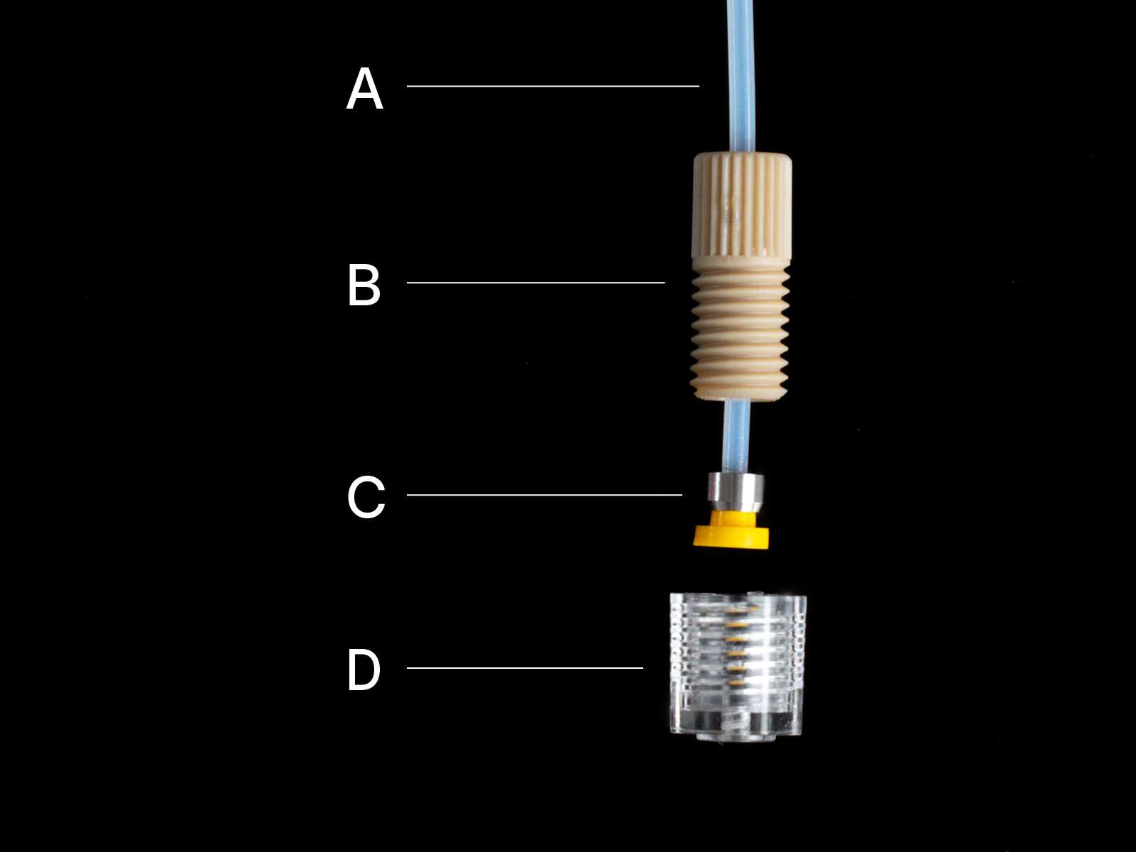
Flangeless 1/4-28 capillary tube interface - Disassembled
Nominal Size - 1/4-28
- The most widely available option, commonly found in other instrumentation.
Tubing - 1/16” PTFE (A)
- 1/16” outer diameter allows for a good balance of availability, flexibility, and inner diameter options.
- PTFE is a low surface energy plastic with good chemical compatibility and bend radius.
Nut - 1/4-28 PEEK with the headless knurl (B)
- PEEK is a robust plastic that threads easily into the thermoplastics ports that we produce here at Parallel.
- The “headless" configuration has a smaller outer diameter, allowing for tighter spacing from interface to interface than the standard variety.
Ferrule - Super Flangeless 1/16” ID ETFE / Stainless steel (C)
- ETFE is one of the softest ferrule varieties available, creating a good fluidic seal with minimal torque requirements.
- The “Super Flangeless” ferrule has a stainless steel ring that prevents the capillary tube from twisting during installation. This seems minor, but trust us, it can be critical to making sure your chip stays in position during use.
Port - Parallel Fluidics 1/4-28 port (D)
- All Parallel Hardware interfaces are welded directly to your microfluidic device in the same polymer as your device itself. This helps to ensure maximum chemical and biological compatibility for your application.
Luer link to Luer section
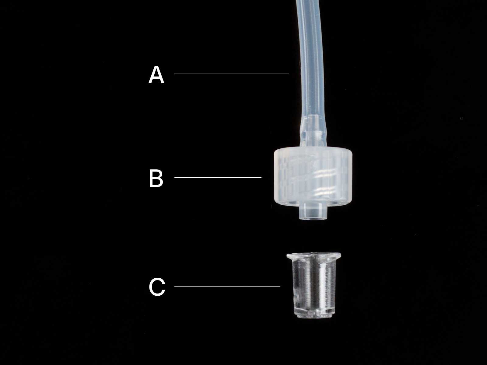
A luer interface is a simple style of fluid connection that is widely used in the medical device industry and controlled by the ISO 80369-7 standard. The connection itself consists of soft elastomer tubing (A), a male plug (B), and a female socket (C), both of which share a taper angle of 6% (1.72 degrees per side). In the pictured configuration, called a “luer slip”, the plug and the socket are pressed together to create a liquid-tight seal.
Luers are found in many medical applications, but perhaps the most common is the disposable syringe, where it allows for easy connection to a hypodermic needle. Many adapters are available to combine a luer taper with different fluidic connections, such as barbed and threaded fittings. The ubiquity of the luer geometry means that fittings are easy to source, inexpensive, and compatible with many other forms of instrumentation.
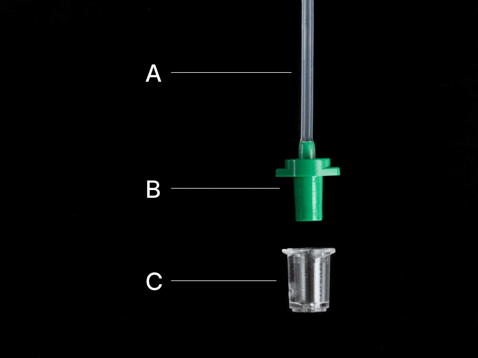
Luer slip tube interface - Disassembled
For microfluidics specifically, “mini-luers” are a smaller version of a luer slip style fitting. They don’t comply with the ISO spec, but they use the same 6% taper in a compact format that is easier to fit into microfluidic applications. While the luer slip is attractive in its simplicity, the fittings can leak if they experience too much pressure or if the user does not assemble them tightly enough.
A more robust solution is the “luer lock” configuration, where a female thread is added to the plug side of the fitting and tabs are added to the socket side. In this configuration, twisting the thread creates a tighter seal between the tapered surfaces, reducing the chance of leaks when the fitting is under pressure.
According to the ISO spec, all luer fittings must be tested to 43.5 psi (300 kPa) of pressure tolerance when properly installed. However, this is just for the luer taper portion of the connector. The most common setup for microfluidic applications would be for a luer fitting to connect to elastomer tubing via a barb adapter (as pictured below). Soft elastomer tubing is much easier to handle than rigid capillary tubing, but it does not have the same level of pressure and chemical compatibility. If a barb adapter is used to connect the luer to soft tubing, the working pressure of the system will likely be dictated by the barb/tubing combination and may be lower than the rated pressure according to the luer ISO specification.
Pros
- Inexpensive
- Compatible with many adapters and other systems
- Easy to handle
Cons
- Large head diameter can be problematic for tight spacing
- Large dead volume
- Low pressure tolerance
- Limited material options (polypropylene, polycarbonate, and nylon)
Suggested combination
Like capillary tube interfaces, the world of luer fittings can be confusing. We recommend sticking with luer lock style fittings over the luer slip style. The configuration below is a good starting point for many microfluidic applications without stringent compatibility requirements for chemicals or small molecules.
Suggested combination: Luer lock tube interface - Disassembled
Nominal Size - 1/16”
- A readily available option that is also compatible with 1.5mm inner diameter tubing.
Tubing - 1/16” Tygon S-3 E-3603 lab tubing (A)
- 1/16” diameter allows for a good balance of availability, flexibility, and pressure tolerance.
- USP Class VI rated for biocompatibility.
Plug - Luer to 1/16” barb (B)
- Polypropylene is a soft, translucent plastic with good chemical compatibility.
- The barb fitting allows the luer to adapt to soft tubing.
Socket - Parallel Fluidics luer-lock port (C)
- All Parallel Hardware interfaces are welded directly to your microfluidic device in the same polymer as your device itself. This helps to ensure maximum chemical and biological compatibility for your application.
Quick tip - Tube management link to Quick tip - Tube management section
Pre-twisting your luer fittings in the opposite direction of installation before attaching them to a device can prevent mechanical stress and ensure that your device stays put.
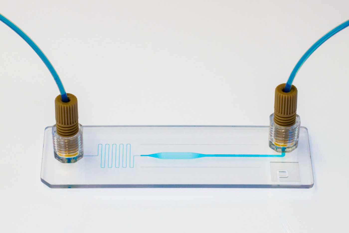
A slide format microfluidic device with embedded 1/4-28 capillary tube interfaces.
Embedded Hardware link to Embedded Hardware section
At Parallel Fluidics we can embed luer-lock ports and capillary tube ports directly to your device for leak-free connections to instrumentation. Instead of using glues or adhesive tapes that can contaminate assays, our tubing interfaces are welded directly to the fluidic layer in the same polymer as the device body. It’s easy to incorporate Parallel Hardware into your custom device. Just include CAD models from our Hardware Library in your device and upload your design to get a same-day quote.
Our engineering team is always happy to chat about your interfacing needs. Schedule a call to learn more.