Design Guide
Part of Resources
Part of Resources
Design guidelines to make your microfluidic device ready for manufacturing.
Microfluidics is a technology that miniaturizes scientific studies to make them faster and more precise. At the heart of every microfluidic system, is a device – sometimes called a chip or cartridge – that contains tiny channels and features designed to manipulate a liquid sample. The size and shape of these features can be customized for different tasks like sorting cells, creating droplets, and culturing tissue at microscopic scales. From disease testing to drug discovery, microfluidic systems are powering the next generation of life science tools.
The power of microfluidics comes from the scientific insights that happen inside the device. However, challenges in manufacturing the device itself often add the most cost and time to the product development process. With Parallel Fluidics, your team can avoid the biggest risks of building a microfluidic product and stay focused on the science.
Accelerate your design/test/build cycle with industry-leading 3-day turnaround. Once your design is locked in, you can ramp up from a few prototypes to hundreds of devices per month with a single click.
Device performance can vary wildly when switching from one material to another. With Transition Molding, you start with production-grade resins from day one, eliminating risk and shortening the time to scale-up.
Your real technology is what’s happening inside your chip. Parallel Hardware lets you prioritize your scientific challenges instead of reinventing the wheel to control fluid flow.
The design guide outlines best practices for every aspect of the On-Demand Manufacturing process. Following the suggestions will guarantee the lowest cost and best chance of success for your project.
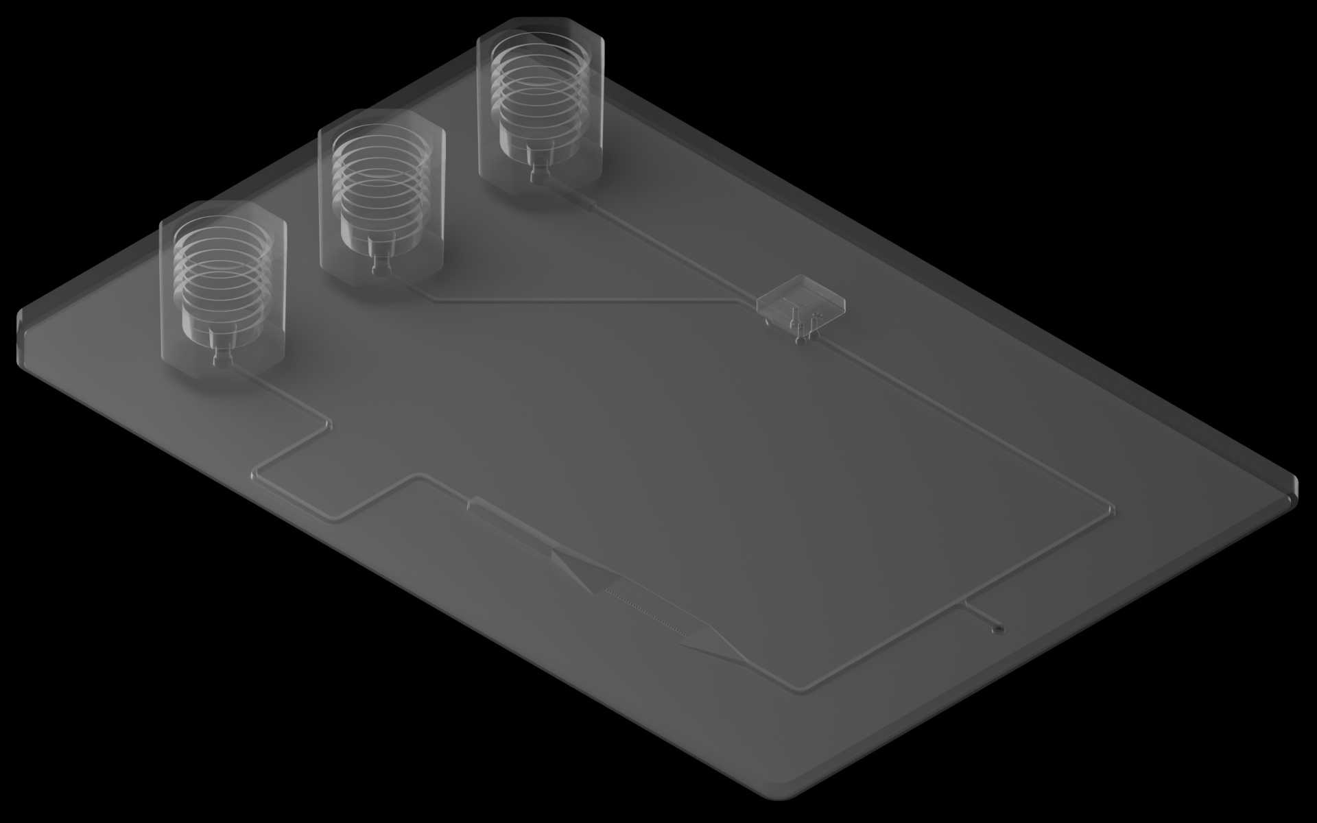
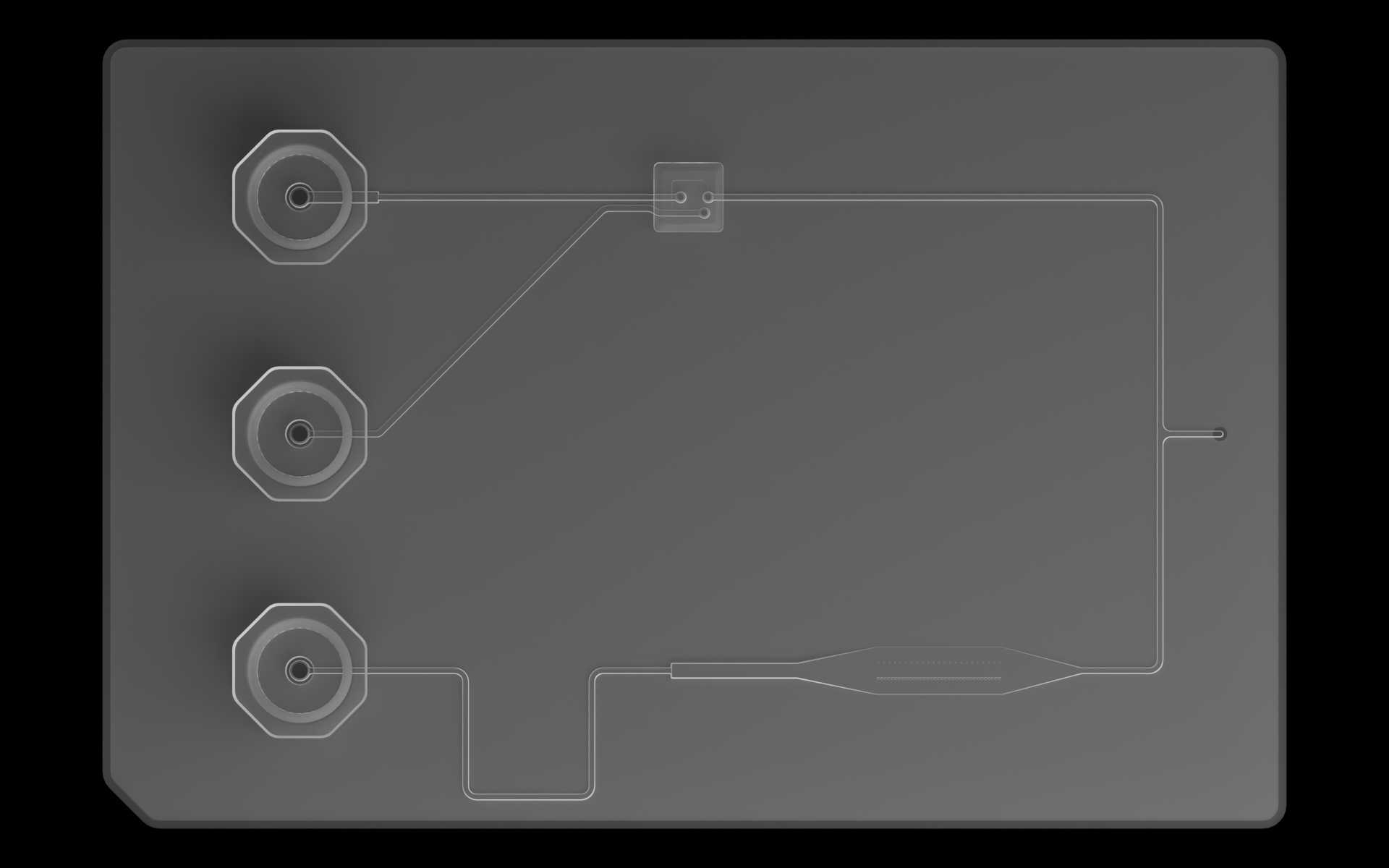
We’ll use the reference device throughout the design guide to highlight best practices for On-Demand Manufacturing.