Computer-aided design (CAD) programs let you define the channel sizes, microfeature geometry, and footprint of your microfluidic device.
2D CAD - Easy to learn, but imprecise
Parametric 2D CAD tools like AutoCAD and DraftSight give you precise control of your microfeature dimensions. They are the go-to programs for designing photomasks used to fabricate PDMS devices by soft lithography. However, they don’t capture the full picture of your device in three dimensions, making them incompatible with other fabrication methods.

2D microfluidic device in AutoCAD.
3D CAD - Powerful, but complicated
3D CAD programs are the industry standard for defining the exact details of your microfluidic device. The most common packages used by microfluidic technology developers are SolidWorks from Dassault Systèmes and Autodesk Fusion. While extremely powerful, the steep learning curve can frustrate new users.
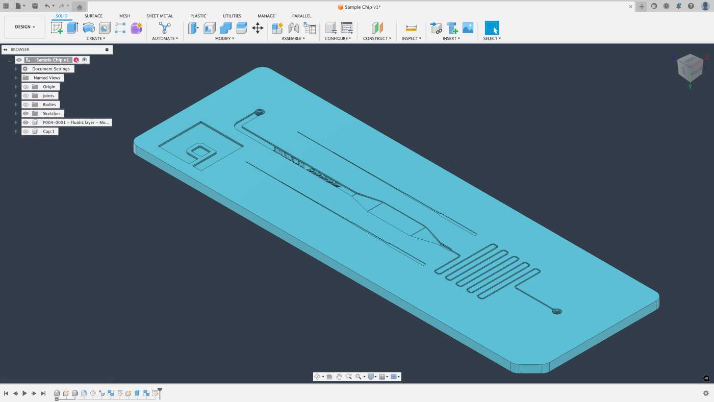
3D microfluidic device in Fusion 360.
Schedule a workshop with our engineering team to work through the challenges of 2D and 3D CAD for microfluidics.